
OBJECTIVES :
The aim of this chapter is to gather knowledge about construction, types and principle of operation of 3-phase induction motors. Introduction is dealt before, you can also get here.
CONSTRUCTION :


CONSTRUCTION :

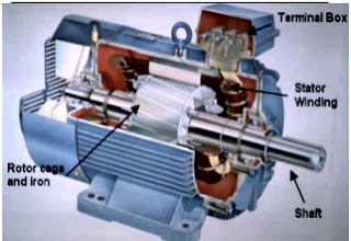
A typical motor consists of two parts namely stator and rotor like other type of motors.
1. An outside stationary stator having coils supplied with AC current to produce a rotating magnetic field,
2. An inside rotor attached to the output shaft that is given a torque by the rotating field.
Stator construction

The stator of an induction motor is laminated iron core with slots similar to a stator of a synchronous machine. Coils are placed in the slots to form a three or single phase winding.
Type of rotors
Rotor is of two different types.
1. Squirrel cage rotor
2. Wound rotor
Squirrel-Cage Rotor :

In the squirrel-cage rotor, the rotor winding consists of single copper or aluminium bars placed in the slots and short-circuited by end-rings on both sides of the rotor. Most of single phase induction motors have Squirrel-Cage rotor. One or 2 fans are attached to the shaft in the sides of rotor to cool the circuit.
Wound Rotor :

In the wound rotor, an insulated 3-phase winding similar to the stator winding wound for the same number of poles as stator, is placed in the rotor slots. The ends of the star-connected rotor winding are brought to three slip rings on the shaft so that a connection can be made to it for starting or speed control.
● It is usually for large 3 phase induction motors.
● Rotor has a winding the same as stator and the end of each phase is connected to a slip ring.
● Compared to squirrel cage rotors, wound rotor motors are expensive and require maintenance of the slip rings and brushes, so it is not so common in industry applications.
PRINCIPLE OF OPERATION
An AC current is applied in the stator armature which generates a flux in the
stator magnetic circuit.
This flux induces an emf in the conducting bars of rotor as they are “cut” by the flux while the magnet is being moved (E = BVL (Faraday’s Law)). A current flows in the rotor circuit due to the induced emf, which in term produces a force, (F = BIL) can be changed to the torque as the output.
In a 3-phase induction motor, the three-phase currents ia, ib and ic, each of equal magnitude, but differing in phase by 120°.
Each phase current produces a magnetic flux and there is physical
120° shift between each flux. The total flux in the machine is the sum of the three fluxes. The summation of the three ac fluxes results in a rotating flux, which turns with constant speed and has constant amplitude. Such a magnetic flux produced by balanced three phase currents flowing in thee-phase windings is called a rotating magnetic flux or rotating magnetic field (RMF). RMF rotates with a constant speed (Synchronous Speed).
Existence of a RFM is an essential condition for the operation of an induction motor. If stator is energized by an ac current, RMF is generated due to the applied current to the stator winding. This flux produces magnetic field and the field revolves in the air gap between stator and rotor. So, the magnetic field induces a voltage in the short-circuited bars of the rotor. This voltage drives current through the bars. The interaction of the rotating flux and the rotor current generates a force that drives the motor and a torque is developed consequently. The torque is proportional with the flux density and the rotor bar current (F=BLI).
The motor speed is less than the synchronous speed. The direction of the rotation of the rotor is the same as the direction of the rotation of the revolving magnetic field in the air gap. However, for these currents to be induced, the speed of the physical rotor and the speed of the rotating magnetic field in the stator must be different, or else the magnetic field will not be moving relative to the rotor conductors and no currents will be induced.
If by some chance this happens, the rotor typically slows slightly until a current is re-induced and then the rotor continues as before. This difference between the speed of the rotor and speed of the rotating magnetic field in the stator is called slip. It is unitless and is the ratio between the relative speed of the magnetic field as seen by the rotor the (slip speed) to the speed of the rotating stator field.
Due to this an induction motor is
sometimes referred to as an asynchronous machine.
SLIP
The relationship between the supply frequency, f, the number of poles, p, and the synchronous speed (speed of rotating field), Ns is given by 120f/p
The stator magnetic field (rotating magnetic field) rotates at a speed, ns, the synchronous speed. If, Nr= speed of the rotor, the slip, S for an induction motor is defined
as S=(Ns-Nr)/ Ns
At stand still, rotor does not rotate ,
Nr = 0, so S = 1.
At synchronous speed,
Nr = NS, S= 0
The mechanical speed of the rotor, in terms of slip and synchronous speed is given by,
Nr=(1-S)Ns
Frequency of Rotor Current and Voltage With the rotor at stand-still, the frequency of the induced voltages and currents is the same as that of the stator (supply) frequency, fe.
If the rotor rotates at speed of Nr, then the relative speed is the slip speed:
Nslip=Ns-Nr
Nslip is responsible for induction.
1. An outside stationary stator having coils supplied with AC current to produce a rotating magnetic field,
2. An inside rotor attached to the output shaft that is given a torque by the rotating field.
Stator construction

The stator of an induction motor is laminated iron core with slots similar to a stator of a synchronous machine. Coils are placed in the slots to form a three or single phase winding.
Type of rotors
Rotor is of two different types.
1. Squirrel cage rotor
2. Wound rotor
Squirrel-Cage Rotor :

Wound Rotor :

In the wound rotor, an insulated 3-phase winding similar to the stator winding wound for the same number of poles as stator, is placed in the rotor slots. The ends of the star-connected rotor winding are brought to three slip rings on the shaft so that a connection can be made to it for starting or speed control.
● It is usually for large 3 phase induction motors.
● Rotor has a winding the same as stator and the end of each phase is connected to a slip ring.
● Compared to squirrel cage rotors, wound rotor motors are expensive and require maintenance of the slip rings and brushes, so it is not so common in industry applications.
PRINCIPLE OF OPERATION
An AC current is applied in the stator armature which generates a flux in the
stator magnetic circuit.
This flux induces an emf in the conducting bars of rotor as they are “cut” by the flux while the magnet is being moved (E = BVL (Faraday’s Law)). A current flows in the rotor circuit due to the induced emf, which in term produces a force, (F = BIL) can be changed to the torque as the output.
In a 3-phase induction motor, the three-phase currents ia, ib and ic, each of equal magnitude, but differing in phase by 120°.
Each phase current produces a magnetic flux and there is physical
120° shift between each flux. The total flux in the machine is the sum of the three fluxes. The summation of the three ac fluxes results in a rotating flux, which turns with constant speed and has constant amplitude. Such a magnetic flux produced by balanced three phase currents flowing in thee-phase windings is called a rotating magnetic flux or rotating magnetic field (RMF). RMF rotates with a constant speed (Synchronous Speed).
Existence of a RFM is an essential condition for the operation of an induction motor. If stator is energized by an ac current, RMF is generated due to the applied current to the stator winding. This flux produces magnetic field and the field revolves in the air gap between stator and rotor. So, the magnetic field induces a voltage in the short-circuited bars of the rotor. This voltage drives current through the bars. The interaction of the rotating flux and the rotor current generates a force that drives the motor and a torque is developed consequently. The torque is proportional with the flux density and the rotor bar current (F=BLI).
The motor speed is less than the synchronous speed. The direction of the rotation of the rotor is the same as the direction of the rotation of the revolving magnetic field in the air gap. However, for these currents to be induced, the speed of the physical rotor and the speed of the rotating magnetic field in the stator must be different, or else the magnetic field will not be moving relative to the rotor conductors and no currents will be induced.
If by some chance this happens, the rotor typically slows slightly until a current is re-induced and then the rotor continues as before. This difference between the speed of the rotor and speed of the rotating magnetic field in the stator is called slip. It is unitless and is the ratio between the relative speed of the magnetic field as seen by the rotor the (slip speed) to the speed of the rotating stator field.
Due to this an induction motor is
sometimes referred to as an asynchronous machine.
SLIP
The relationship between the supply frequency, f, the number of poles, p, and the synchronous speed (speed of rotating field), Ns is given by 120f/p
The stator magnetic field (rotating magnetic field) rotates at a speed, ns, the synchronous speed. If, Nr= speed of the rotor, the slip, S for an induction motor is defined
as S=(Ns-Nr)/ Ns
At stand still, rotor does not rotate ,
Nr = 0, so S = 1.
At synchronous speed,
Nr = NS, S= 0
The mechanical speed of the rotor, in terms of slip and synchronous speed is given by,
Nr=(1-S)Ns
Frequency of Rotor Current and Voltage With the rotor at stand-still, the frequency of the induced voltages and currents is the same as that of the stator (supply) frequency, fe.
If the rotor rotates at speed of Nr, then the relative speed is the slip speed:
Nslip=Ns-Nr
Nslip is responsible for induction.


