Thursday, September 12, 2019

Difference Between Grounding and Earthing

One of the major difference between the grounding and the earthing is that in grounding, the current carrying part is connected to the ground whereas in earthing the non-current carrying parts is connected to ground. 

Definition of Grounding :-

In grounding, the current carrying parts are directly connected to the ground. The grounding provides the return path for the leakage current and hence protect the power system equipment from damage. 
When the fault occurs in the equipment, the current in all the three phases of the equipment become unbalance.The grounding discharges the fault current to the ground and hence makes the system balance.
The grounding has several advantages like it eliminates the surge voltage and also discharge the over voltage to the ground. The grounding provides the great safety to the equipment and improves the service reliability.

Definition of Earthing :-

The ‘earthing’ means the connection of non-current carrying part of the equipment to the earth. When the fault occurs in the system, then the potential of the non-current part of the equipment raises, and when any human or stray animal touch the body of the equipment, then they may get shocked. 
The earthing discharges the leakage current to the earth and hence avoid the personnel from the electric shock. It also protects the equipment from lighting strokes provides the discharge path for the surge arrester, gap and other devices.
The earthing is achieved by connecting the parts of the installation to the earth by using the earth conductor or earth electrode in intimate contact with the soil placed with some distance below the ground level.

Key Differences Between Grounding and Earthing :-

  1. The earthing is defined as the connection of the non-current carrying part like the body of the equipment or enclosure to earth. In grounding the current carrying part like neutral of the transformer is directly connected to the ground.
  2. For grounding, the black colour wire is used, and for earthing the green colour, the wire is used.
  3. The grounding balanced the unbalanced load whereas the earthing protect the equipment and human from an electrical shock.
  4. The grounding wire is placed between the neutral of the equipment and the earth whereas in earthing the earth electrode is placed between the equipment body and the earth pit which is placed under the ground.
  5.  In grounding the equipment is not physically connected to the ground, and the current is not zero on the ground, whereas in earthing the system is physically connected to the ground and it is at zero potential.
  6. The grounding gives the path to an unwanted current and hence protects the electrical equipment from damage, whereas the earthing decrease the high potential of electrical equipment which is caused by a fault and thus protects the human body from the electrical shock.
  7. The grounding is classified into three types. They are the solid grounding, resistance grounding and reactance grounding. Earthing can be done in five ways.The different methods of earthing are the pipe earthing, plate earthing, rod earthing, earthing through tap and strip earthing.
Wednesday, September 11, 2019

Which is more dangerous to the human body: AC or DC current and voltage?

The effects of both on the human body differ, but one is more hazardous than the other.


No matter what, if either AC or DC comes in contact with the human body, it can be hazardous. The actual effect varies, though, as it depends upon several different factors, including the amount of current administered, duration of which it was in contact with the body, pathway of the current, voltage applied, and impedance of the body itself. 

All of that being said, if it comes down to one or the other, AC can generally be viewed as the more dangerous of the two currents — here’s why:

1) To start off, in order for both currents to have the same effect on the human body, the magnitude of DC flow of constant strength needs to be two to four times great than AC; that is, more DC current is needed to induce the same amount of physical damage as AC current. This is because the effect of the currents on the body is a direct result of the excitatory actions of its magnitude — specifically, the actual making and breaking of the current itself. Such excitatory actions include nerve / muscle stimulation, induction of cardiac atrial or ventricular fibrillation, and more. 

For DC to produce the same effect as AC on the human body, its flow of constant strength must be two to four times that being administered by the AC.

2) When death by electric shock occurs, it’s typically due to ventricular fibrillation, and the likelihood of a human suffering this sort of life-ending injury is much higher when coming in contact with an AC than a DC due to the fact that the human body’s threshold of DC-caused ventricular fibrillation is several times higher than for AC. 

3) Generally speaking, the human body’s impedance is higher for DC, and it only decreases when the frequency increase. As such, the severity of electric shock is less when in contact with DC than it is with AC. 

4) It’s easier to let go / remove contact with “live” parts in the case of DC than AC. This runs counter to the popular belief that because the alternating cycles of an AC current pass through zero, the individual is afforded enough time to pull their limb / body away from the part itself, whereas with the constant flow of the DC current, there is no frequency oscillations that afford the brief moment for the person to pull their body away. The basis for this argument can be sourced in the “let-go” experiment, which was reported in the same aforementioned IEC publication 60479. In it, the lowest level of current that could safely pass through a human body was administered through an electrode held in a test person’s hand; it was enough current to make the person unable to open his hand and drop the electrode. 

Without getting into all of the details of the actual experiment, the conclusion was that the test subjects found it easier to release the electrode when DC was administered rather than AC. 

Now, while it can be surmised that AC is more dangerous than DC, the safest solution is to avoid contact with any and all high-voltage electrical conductors, no matter the type of electrical current. As mentioned at the beginning of the article, any contact with an electrical current can be hazardous. 

Friday, June 14, 2019

Polyphase Induction Motor (Construction, Types and Principle of operation)

OBJECTIVES :


The aim of this chapter is to gather knowledge about construction, types and principle of operation of 3-phase induction motors. Introduction is dealt before, you can also get here.

CONSTRUCTION :


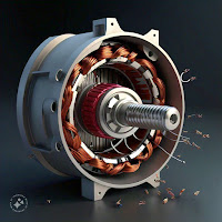
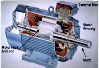
A typical motor consists of two parts namely stator and rotor like other type of motors.
1. An outside stationary stator having coils supplied with AC current to produce a rotating magnetic field,
2. An inside rotor attached to the output shaft that is given a torque by the rotating field.

Stator construction


The stator of an induction motor is laminated iron core with slots similar to a stator of a synchronous machine. Coils are placed in the slots to form a three or single phase winding.

Type of rotors 

Rotor is of two different types.
1. Squirrel cage rotor
2. Wound rotor

Squirrel-Cage Rotor :


In the squirrel-cage rotor, the rotor winding consists of single copper or aluminium bars placed in the slots and short-circuited by end-rings on both sides of the rotor. Most of single phase induction motors have Squirrel-Cage rotor. One or 2 fans are attached to the shaft in the sides of rotor to cool the circuit.

Wound Rotor :


In the wound rotor, an insulated 3-phase winding similar to the stator winding wound for the same number of poles as stator, is placed in the rotor slots. The ends of the star-connected rotor winding are brought to three slip rings on the shaft so that a connection can be made to it for starting or speed control.
● It is usually for large 3 phase induction motors.
● Rotor has a winding the same as stator and the end of each phase is connected to a slip ring.
● Compared to squirrel cage rotors, wound rotor motors are expensive and require maintenance of the slip rings and brushes, so it is not so common in industry applications.

PRINCIPLE OF OPERATION

An AC current is applied in the stator armature which generates a flux in the
stator magnetic circuit.
                                This flux induces an emf in the conducting bars of rotor as they are “cut” by the flux while the magnet is being moved (E = BVL (Faraday’s Law)). A current flows in the rotor circuit due to the induced emf, which in term produces a force, (F = BIL) can be changed to the torque as the output.
             In a 3-phase induction motor, the three-phase currents ia, ib and ic, each of equal magnitude, but differing in phase by 120°.
            Each phase current produces a magnetic flux and there is physical
120° shift between each flux. The total flux in the machine is the sum of the three fluxes. The summation of the three ac fluxes results in a rotating flux, which turns with constant speed and has constant amplitude. Such a magnetic flux produced by balanced three phase currents flowing in thee-phase windings is called a rotating magnetic flux or rotating magnetic field (RMF). RMF rotates with a constant speed (Synchronous Speed).
                           Existence of a RFM is an essential condition for the operation of an induction motor. If stator is energized by an ac current, RMF is generated due to the applied current to the stator winding. This flux produces magnetic field and the field revolves in the air gap between stator and rotor. So, the magnetic field induces a voltage in the short-circuited bars of the rotor. This voltage drives current through the bars. The interaction of the rotating flux and the rotor current generates a force that drives the motor and a torque is developed consequently. The torque is proportional with the flux density and the rotor bar current (F=BLI).
              The motor speed is less than the synchronous speed. The direction of the rotation of the rotor is the same as the direction of the rotation of the revolving magnetic field in the air gap. However, for these currents to be induced, the speed of the physical rotor and the speed of the rotating magnetic field in the stator must be different, or else the magnetic field will not be moving relative to the rotor conductors and no currents will be induced.
                                    If by some chance this happens, the rotor typically slows slightly until a current is re-induced and then the rotor continues as before. This difference between the speed of the rotor and speed of the rotating magnetic field in the stator is called slip. It is unitless and is the ratio between the relative speed of the magnetic field as seen by the rotor the (slip speed) to the speed of the rotating stator field.
            Due to this an induction motor is
sometimes referred to as an asynchronous machine.

SLIP

The relationship between the supply frequency, f, the number of poles, p, and the synchronous speed (speed of rotating field), Ns is given by 120f/p

The stator magnetic field (rotating magnetic field) rotates at a speed, ns, the synchronous speed. If, Nr= speed of the rotor, the slip, S for an induction motor is defined
as S=(Ns-Nr)/ Ns
At stand still, rotor does not rotate ,
 Nr = 0, so S = 1.

At synchronous speed,
Nr = NS, S= 0
The mechanical speed of the rotor, in terms of slip and synchronous speed is given by,
Nr=(1-S)Ns
 Frequency of Rotor Current and Voltage With the rotor at stand-still, the frequency of the induced voltages and currents is the same as that of the stator (supply) frequency, fe.
 If the rotor rotates at speed of Nr, then the relative speed is the slip speed:
Nslip=Ns-Nr
Nslip is responsible for induction.

Sunday, June 9, 2019

SCR [V-I Characteristics]

A detailed study of the characteristics reveal that the thyristor has three basic modes of operation, namely the reverse blocking mode, forward blocking (off-state) mode and forward conduction (on-state) mode. Which are discussed in details below :


Reverse Blocking Mode of Thyristor

Cathode is made positive with respect to anode. Junctions J1 and J3 are reverse biased whereas the junction J2 is forward biased. The behavior of the thyristor here is similar to that of two diodes are connected in series with reverse voltage applied across them. As a result only a small leakage current of the order of a few μAmps flows.


This is the reverse blocking mode or the off-state, of the thyristor. If the reverse voltage is now increased, then at a particular voltage, known as the critical breakdown voltage VBR, an avalanche occurs at J1 and J3 and the reverse current increases rapidly. 

A large current associated with VBR gives rise to more losses in the SCR, which results in heating. This may lead to thyristor damage as the junction temperature may exceed its permissible temperature rise. It should, therefore, be ensured that maximum working reverse voltage across a thyristor does not exceed VBR. When reverse voltage applied across a thyristor is less than VBR, the device offers very high impedance in the reverse direction. The SCR in the reverse blocking mode may therefore be treated as open circuit.


Forward Blocking Mode


Now considering the anode is positive with respect to the cathode, with gate kept in open condition. The thyristor is now said to be forward biased as shown the figure below.

As we can see the junctions J1 and J3arenow forward biased but junction J2 goes into reverse biased condition. In this particular mode, a small current, called forward leakage current is allowed to flow initially as shown in the diagram for characteristics of thyristor. Now, if we keep on increasing the forward biased anode to cathode voltage.

In this particular mode, the thyristor conducts currents from anode to cathode with a very small drop of potential across it. A thyristor is brought from forward blocking mode to forward conduction mode by turning it on by exceeding the forward break over voltage or by applying a gate pulse between gate and cathode. In this mode, thyristor is in on-state and behaves like a closed switch. Voltage drop across thyristor in the on state is of the order of 1 to 2 V depending beyond a certain point, then the reverse biased junction J2 will have an avalanche breakdown at a voltage called forward break over voltage VB0 of the thyristor. But, if we keep the forward voltage less than VBO, we can see from the characteristics of thyristor, that the device offers a high impedance. Thus even here the thyristor operates as an open switch during the forward blocking mode.


Forward Conduction Mode


When the anode to cathode forward voltage is increased, with gate circuit open, the reverse junction J2 will have an avalanche breakdown at forward break over voltage VBO leading to thyristor turn on.
Once the thyristor is on we can see from the diagram for characteristics of thyristor. 


In this mode of operation, the thyristor conducts maximum current with minimum voltage drop, this is known as the forward conduction forward conduction or the turn on mode of the thyristor.

Tuesday, June 4, 2019

SCR (Silicon Controlled Rectifier) {Introduction, Symbol & why Silicon is used?}

The idea for the thyristor is not new. The idea for the device was first put forward in 1950 by William Shockley, one of the inventors of the transistor.


What is a thyristor?


The thyristor has a p-n-p-n structure with the outer layers with their electrodes referred to as the anode (n-type) and the cathode (p-type). The control terminal of the SCR is named the gate and it is connected to the p-type layer that adjoins the cathode layer.

Why Silicon in a thyristor?

Silicon is the ideal choice because of its overall properties. It is able to handle the voltage and currents required for high power applications. Additionally it has good thermal properties. The second major reason is that silicon technology is well established and it is widely used for a variety of semiconductor electronics components. As a result it is very cheap and easy for semiconductor manufacturers to use.


Thyristor symbols & basics

The thyristor or silicon controlled rectifier, SCR is a device that has a number of unusual characteristics. It has three terminals: Anode, cathode and gate, reflecting thermionic valve / vacuum tube technology. As might be expected the gate is the control terminal while the main current flows between the anode and cathode.


As can be imagined from its circuit symbol shown below, the device is a "one way device" giving rise to the GE name for it the silicon controlled rectifier. Therefore when the device is used with AC, it will only conduct for a maximum of half the cycle.
In operation, the thyristor or SCR will not conduct initially. It requires a certain level of current to flow in the gate to "fire" it. Once fired, the thyristor will remain in conduction until the voltage across the anode and cathode is removed - this obviously happens at the end of the half cycle over which the thyristor conducts. The next half cycle will be blocked as a result of the rectifier action. It will then require current in the gate circuit to fire the SCR again.
The silicon controlled rectifier, SCR or thyristor symbol used for circuit diagrams or circuit seeks to emphasis its rectifier characteristics while also showing the control gate. As a result the thyristor symbol shows the traditional diode symbol with a control gate entering near the junction.

Wednesday, January 30, 2019

Relays working in Electric Traction

A relay is a sensitive device provided to ensure the proper functioning of an apparatus either in the electrical circuit or in the fluid circuit and to safe guard the apparatus during any abnormalities.

*As per working principle in locomotive relays may be classified :
1. Electrical relay ( which work with electrical supply)
2. Mechanical relay ( which works with air or oil flow or pressure or by heat etc.)

Since relays are switches the terminology applied to the switches is also applied to the energising the coil in relays. A relay will switch one or more poles, each of whose contacts can be thrown by one of the three ways -

Normally Open (NO) :
Contacts connect the circuit when the relay activated, the circuit is disconnected when the relay is inactive. It is also called a Form A contact or  "Make contact".

Normally Close (NC) :
Contacts are disconnect the circuit when the relay activated, the circuit is connected when the relay is inactive. It is also called Form B contact or " Brake contact".

Change Over (CO) or Double throw (DT) contact :
Contacts control two circuits, one normally open contact and one normally closed contact with a common terminals. It is also called Form C contact or brake before make contact. If this type of contact utilizes a make before break functionally, then it is called a Form D contact.

ELECTRICAL RELAYS
An electrical relay is sensitive to electricity and it is of two kinds :
(a). Voltage or Tension relay
(b). Current or Intensity relay

A. Voltage relay or tension relay :

The relay ,which works on voltage, is known as voltage relay. They are two kinds :
(1). No or /low voltage relay and
(2). Over voltage relay.

(1). No or Low voltage relay : This relay checks the voltage of auxiliary transformer TFWA. This relay is connected between the two terminals of the source supply of TFWA. The interlock of this relay is provided in the control circuit (Q-44 branch). In case there is no or low voltage at the source of supply, it de-energised and its interlock opens on the control circuit of Q-44 to open D.J.
USE ON LOCO - Q-30.

(2). Over voltage relay : This relay is connected across the two terminals (+Ve & -Ve of RSI block and its interlock is provided in the control circuit. In case there is over voltage in the traction motor its interlock closes on the control circuit and relay Q-51 energises cause auto regresssion of G.R.
USE ON LOCO - Q-20.

B. Current or intensity relay : 

The  current or intensity relay is that which is sensitive to the flow of current. They are of two kinds :
1. Over current relay
2. Difference of current or current differential relay.

(1). Over current relay : This relay is provided in the feeding and traction power circuit in which the over current is to be checked and the interlock is provided in the control circuit. If there is over current in the concerning circuit the relay energises and the interlock of the relay will open in the control circuit of DJ to open it.
USE ON LOCO - QLM, QRSI-1 and QRSI-2 and also QLAon some locos.

(2). Difference of current or current differential relay : This relay is connected in the traction power circuit with the two groups of traction motors in series in which the difference of current  is to be checked, and the interlock is provided in the control circuit. If there isa difference of current of 160Amps between the groups of motors its interlock will close in the control circuit of Q-48 to cause auto regression of G.R., auto sanding and LSP glowing.
USE ON LOCO - QD1 and QD2.

MECHANICAL RELAYS 
The relays, which work by mechanical means, are called mechanical relays. The controlling device is provided in the circuit in which circulation, pressure, temperature or speed is to be checked and the interlock is provided in the control circuit. These relays are of four types namely :
(a). Circulation relay
(b). Pressure relay
(c). Temperature relay
(d). Speed relay

A. Circulation relay : The controlling device of this type of relay is provided in the fluid (air). Circuit to check air circulation and the interlock is provided in the control circuit.
If there is no circulation or improper circulation of fluid (air) its interlock will open in the control circuit to open D.J.
USE ON LOCO : QVSI-1, QVSI-2, QVSL-1, QVSL-2, QVRH, QVMT1, QVMT-2 (all checks air circulation).

B. Pressure relay/Pressure switch : The controlling device of this type of relay is provided on the pipeline of the fluid (air circulation/oil) and the interlock is provided in the control circuit.
USE ON LOCO : QPH (check pressure of oil), QPDJ (check pressure of air)
N.B. Pressure switches provided on loco are RGCP,RGEB, RGAF, P-1, P-2 etc.
C. Temperature relay : Not provided on Loco
D. Speed relay : Not provided on Loco

OTHER RELAYS PROVIDED ON LOCO 

A. Safety relay: The relays used on the control circuit of DJ and their normally closed, inter locks are provided in MTDJ branch to open DJ immediately, are called the safety relays.
All the safety relays are provided with a red target of connecting relays droops. To reset the red target it is necessary to operate the resetting knob.
USE ON LOCO : QLM,QRSI-1, QRSI-2, QOA, QOA, QOP-1 and QOP-2, on some loco QLA also.

B. Temporised or time lag relay : The relays which, after energizing or de-energising takes some time (A few seconds) to close or open its interlock on the control circuit, is called a temporised or time lag relay.
These types of relays may either be electrically time lag or mechanically time lag.
a). On delay relay - QTD 105, QTD 106, QSVM (in STC loco)
b). Off delay relay - Q-118(Temporised for 5 sec.), Q-44 (Temporised for 0.6 sec.)
C). Signalling Relays - The relay used for indication of different signalling lamps are called signalling relays.
USE ON LOCO : QV-60, QV-61, QV-62, QV-63, QV-64, QVLSOL etc.

ELECTRICAL FUSE

Hello readers, I am here with the topic 'Electrical fuse' from power system. Let's start this, firstly we will discuss its...